Contents
- 1 PPU Registers
- 2 Summary
- 3 Ports
- 4 References
- 5 Pattern tables
- 6 Addressing
- 7 OAM
- 8 See also
- 9 References
- 10 Nametables
- 11 Mirroring
- 12 Background evaluation
- 13 See also
- 14 Attribute tables
- 15 Worked example
- 16 Glitches
- 17 See also
- 18 Palettes
- 19 Memory Map
- 20 Palettes
- 21 Backdrop color (palette index 0) uses
- 22 The background palette hack
- 23 Color names
- 24 See also
- 25 Memory map
- 26 Hardware mapping
PPU Registers
The PPU exposes eight memory-mapped registers to the CPU. These nominally sit at $2000 through $2007 in the CPU's address space, but because they're incompletely decoded, they're mirrored in every 8 bytes from $2008 through $3FFF, so a write to $3456 is the same as a write to $2006.
Immediately after powerup, the PPU isn't necessarily in a usable state. The program needs to do a few things to get it going; see PPU power up state and Init code.
Summary
| Common Name | Address | Bits | Notes |
|---|---|---|---|
| PPUCTRL | $2000 | VPHB SINN | NMI enable (V), PPU master/slave (P), sprite height (H), background tile select (B), sprite tile select (S), increment mode (I), nametable select (NN) |
| PPUMASK | $2001 | BGRs bMmG | color emphasis (BGR), sprite enable (s), background enable (b), sprite left column enable (M), background left column enable (m), greyscale (G) |
| PPUSTATUS | $2002 | VSO- ---- | vblank (V), sprite 0 hit (S), sprite overflow (O); read resets write pair for $2005/$2006 |
| OAMADDR | $2003 | aaaa aaaa | OAM read/write address |
| OAMDATA | $2004 | dddd dddd | OAM data read/write |
| PPUSCROLL | $2005 | xxxx xxxx | fine scroll position (two writes: X scroll, Y scroll) |
| PPUADDR | $2006 | aaaa aaaa | PPU read/write address (two writes: most significant byte, least significant byte) |
| PPUDATA | $2007 | dddd dddd | PPU data read/write |
| OAMDMA | $4014 | aaaa aaaa | OAM DMA high address |
Ports
The PPU has an internal data bus that it uses for communication with the CPU.
This bus, called _io_db in Visual 2C02 and PPUGenLatch in FCEUX,[1] behaves as an 8-bit dynamic latch due to capacitance of very long traces that run to various parts of the PPU.
Writing any value to any PPU port, even to the nominally read-only PPUSTATUS, will fill this latch.
Reading any readable port (PPUSTATUS, OAMDATA, or PPUDATA) also fills the latch with the bits read.
Reading a nominally "write-only" register returns the latch's current value, as do the unused bits of PPUSTATUS.
This value begins to decay after a frame or so, faster once the PPU has warmed up, and it is likely that values with alternating bit patterns (such as $55 or $AA) will decay faster.[2]
Controller ($2000) > write
- Common name: PPUCTRL
- Description: PPU control register
- Access: write
Various flags controlling PPU operation
7  bit  0
---- ----
VPHB SINN
|||| ||||
|||| ||++- Base nametable address
|||| ||    (0 = $2000; 1 = $2400; 2 = $2800; 3 = $2C00)
|||| |+--- VRAM address increment per CPU read/write of PPUDATA
|||| |     (0: add 1, going across; 1: add 32, going down)
|||| +---- Sprite pattern table address for 8x8 sprites
||||       (0: $0000; 1: $1000; ignored in 8x16 mode)
|||+------ Background pattern table address (0: $0000; 1: $1000)
||+------- Sprite size (0: 8x8 pixels; 1: 8x16 pixels)
|+-------- PPU master/slave select
|          (0: read backdrop from EXT pins; 1: output color on EXT pins)
+--------- Generate an NMI at the start of the
           vertical blanking interval (0: off; 1: on)
Equivalently, bits 1 and 0 are the most significant bit of the scrolling coordinates (see Nametables and PPUSCROLL):
7  bit  0
---- ----
.... ..YX
       ||
       |+- 1: Add 256 to the X scroll position
       +-- 1: Add 240 to the Y scroll position
Another way of seeing the explanation above is that when you reach the end of a nametable, you must switch to the next one, hence, changing the nametable address.
After power/reset, writes to this register are ignored for about 30,000 cycles.
If the PPU is currently in vertical blank, and the PPUSTATUS ($2002) vblank flag is still set (1), changing the NMI flag in bit 7 of $2000 from 0 to 1 will immediately generate an NMI. This can result in graphical errors (most likely a misplaced scroll) if the NMI routine is executed too late in the blanking period to finish on time. To avoid this problem it is prudent to read $2002 immediately before writing $2000 to clear the vblank flag.
For more explanation of sprite size, see: Sprite size
Master/slave mode and the EXT pins
When bit 6 of PPUCTRL is clear (the usual case), the PPU gets the palette index for the background color from the EXT pins. The stock NES grounds these pins, making palette index 0 the background color as expected. A secondary picture generator connected to the EXT pins would be able to replace the background with a different image using colors from the background palette, which could be used e.g. to implement parallax scrolling.
Setting bit 6 causes the PPU to output the lower four bits of the palette memory index on the EXT pins for each pixel (in addition to normal image drawing) - since only four bits are output, background and sprite pixels can't normally be distinguished this way. As the EXT pins are grounded on an unmodified NES, setting bit 6 is discouraged as it could potentially damage the chip whenever it outputs a non-zero pixel value (due to it effectively shorting Vcc and GND together). Looking at the relevant circuitry in Visual 2C02, it appears that the background palette hack would not be functional for output from the EXT pins; they would always output index 0 for the background color.
Bit 0 race condition
Be very careful when writing to this register outside vertical blanking if you are using vertical mirroring (horizontal arrangement) or 4-screen VRAM. For specific CPU-PPU alignments, a write that starts on dot 257 will cause only the next scanline to be erroneously drawn from the left nametable. This can cause a visible glitch, and it can also interfere with sprite 0 hit for that scanline (by being drawn with the wrong background).
The glitch has no effect in horizontal or one-screen mirroring. Only writes that start on dot 257 and continue through dot 258 can cause this glitch: any other horizontal timing is safe. The glitch specifically writes the value of open bus to the register, which will almost always be the upper byte of the address. Writing to this register or the mirror of this register at $2100 according to the desired nametable appears to be a functional workaround.
This produces an occasionally visible glitch in Super Mario Bros. when the program writes to PPUCTRL at the end of game logic. It appears to be turning NMI off during game logic and then turning NMI back on once the game logic has finished in order to prevent the NMI handler from being called again before the game logic finishes. Another workaround is to use a software flag to prevent NMI reentry, instead of using the PPU's NMI enable.
Mask ($2001) > write
- Common name: PPUMASK
- Description: PPU mask register
- Access: write
This register controls the rendering of sprites and backgrounds, as well as colour effects.
7  bit  0
---- ----
BGRs bMmG
|||| ||||
|||| |||+- Greyscale (0: normal color, 1: produce a greyscale display)
|||| ||+-- 1: Show background in leftmost 8 pixels of screen, 0: Hide
|||| |+--- 1: Show sprites in leftmost 8 pixels of screen, 0: Hide
|||| +---- 1: Show background
|||+------ 1: Show sprites
||+------- Emphasize red (green on PAL/Dendy)
|+-------- Emphasize green (red on PAL/Dendy)
+--------- Emphasize blue
Render Control
- Bits 3 and 4 enable the rendering of background and sprites, respectively.
- Bits 1 and 2 enable rendering of the background and sprites in the leftmost 8 pixel columns. Setting these bits to 0 will mask these columns, which is often useful in horizontal scrolling situations where you want partial sprites or tiles to scroll in from the left.
- A value of $1E or %00011110 enables all rendering, with no color effects. A value of $00 or %00000000 disables all rendering. It is usually best practice to write this register only during vblank, to prevent partial-frame visual artifacts.
- If either of bits 3 or 4 is enabled, at any time outside of the vblank interval the PPU will be making continual use to the PPU address and data bus to fetch tiles to render, as well as internally fetching sprite data from the OAM. If you wish to make changes to PPU memory outside of vblank (via $2007), you must set both of these bits to 0 to disable rendering and prevent conflicts.
- Disabling rendering (clear both bits 3 and 4) during a visible part of the frame can be problematic. It can cause a corruption of the sprite state, which will display incorrect sprite data on the next frame. (See: Errata) It is, however, perfectly fine to mask sprites but leave the background on (set bit 3, clear bit 4) at any time in the frame.
- Sprite 0 hit does not trigger in any area where the background or sprites are hidden.
Color Control
- Bit 0 controls a greyscale mode, which causes the palette to use only the colors from the grey column: $00, $10, $20, $30. This is implemented as a bitwise AND with $30 on any value read from PPU $3F00-$3FFF, both on the display and through PPUDATA. Writes to the palette through PPUDATA are not affected. Also note that black colours like $0F will be replaced by a non-black grey $00.
- Bits 5, 6 and 7 control a color "emphasis" or "tint" effect. See Colour emphasis for details. Note that the emphasis bits are applied independently of bit 0, so they will still tint the color of the grey image.
Status ($2002) < read
- Common name: PPUSTATUS
- Description: PPU status register
- Access: read
This register reflects the state of various functions inside the PPU. It is often used for determining timing. To determine when the PPU has reached a given pixel of the screen, put an opaque (non-transparent) pixel of sprite 0 there.
7  bit  0
---- ----
VSO. ....
|||| ||||
|||+-++++- Least significant bits previously written into a PPU register
|||        (due to register not being updated for this address)
||+------- Sprite overflow. The intent was for this flag to be set
||         whenever more than eight sprites appear on a scanline, but a
||         hardware bug causes the actual behavior to be more complicated
||         and generate false positives as well as false negatives; see
||         PPU sprite evaluation. This flag is set during sprite
||         evaluation and cleared at dot 1 (the second dot) of the
||         pre-render line.
|+-------- Sprite 0 Hit.  Set when a nonzero pixel of sprite 0 overlaps
|          a nonzero background pixel; cleared at dot 1 of the pre-render
|          line.  Used for raster timing.
+--------- Vertical blank has started (0: not in vblank; 1: in vblank).
           Set at dot 1 of line 241 (the line *after* the post-render
           line); cleared after reading $2002 and at dot 1 of the
           pre-render line.
Notes
- Reading the status register will clear bit 7 mentioned above and also the address latch used by PPUSCROLL and PPUADDR. It does not clear the sprite 0 hit or overflow bit.
- Once the sprite 0 hit flag is set, it will not be cleared until the end of the next vertical blank. If attempting to use this flag for raster timing, it is important to ensure that the sprite 0 hit check happens outside of vertical blank, otherwise the CPU will "leak" through and the check will fail. The easiest way to do this is to place an earlier check for bit 6 = 0, which will wait for the pre-render scanline to begin.
- If using sprite 0 hit to make a bottom scroll bar below a vertically scrolling or freely scrolling playfield, be careful to ensure that the tile in the playfield behind sprite 0 is opaque.
- Sprite 0 hit is not detected at x=255, nor is it detected at x=0 through 7 if the background or sprites are hidden in this area.
- See: PPU rendering for more information on the timing of setting and clearing the flags.
- Some Vs. System PPUs return a constant value in bits 4-0 that the game checks.
- Race Condition Warning: Reading PPUSTATUS within two cycles of the start of vertical blank will return 0 in bit 7 but clear the latch anyway, causing NMI to not occur that frame. See NMI and PPU_frame_timing for details.
OAM address ($2003) > write
- Common name: OAMADDR
- Description: OAM address port
- Access: write
Write the address of OAM you want to access here. Most games just write $00 here and then use OAMDMA. (DMA is implemented in the 2A03/7 chip and works by repeatedly writing to OAMDATA)
Values during rendering
OAMADDR is set to 0 during each of ticks 257-320 (the sprite tile loading interval) of the pre-render and visible scanlines.
The value of OAMADDR when sprite evaluation starts at tick 65 of the visible scanlines will determine where in OAM sprite evaluation starts, and hence which sprite gets treated as sprite 0. The first OAM entry to be checked during sprite evaluation is the one starting at OAM[OAMADDR]. If OAMADDR is unaligned and does not point to the y position (first byte) of an OAM entry, then whatever it points to (tile index, attribute, or x coordinate) will be reinterpreted as a y position, and the following bytes will be similarly reinterpreted. No more sprites will be found once the end of OAM is reached, effectively hiding any sprites before OAM[OAMADDR].
OAMADDR precautions
On the 2C02G, writes to OAMADDR reliably corrupt OAM.[3] This can then be worked around by writing all 256 bytes of OAM.
It is also the case that if OAMADDR is not less than eight when rendering starts, the eight bytes starting at OAMADDR & 0xF8 are copied to the first eight bytes of OAM; it seems likely that this is related. On the Dendy, the latter bug is required for 2C02 compatibility.
It is known that in the 2C03, 2C04, 2C05[4], and 2C07, OAMADDR works as intended. It is not known whether this bug is present in all revisions of the 2C02.
OAM data ($2004) <> read/write
- Common name: OAMDATA
- Description: OAM data port
- Access: read, write
Write OAM data here. Writes will increment OAMADDR after the write; reads during vertical or forced blanking return the value from OAM at that address but do not increment.
Do not write directly to this register in most cases. Because changes to OAM should normally be made only during vblank, writing through OAMDATA is only effective for partial updates (it is too slow), and as described above, partial writes cause corruption. Most games will use the DMA feature through OAMDMA instead.
- Reading OAMDATA while the PPU is rendering will expose internal OAM accesses during sprite evaluation and loading; Micro Machines does this.
- Writes to OAMDATA during rendering (on the pre-render line and the visible lines 0-239, provided either sprite or background rendering is enabled) do not modify values in OAM, but do perform a glitchy increment of OAMADDR, bumping only the high 6 bits (i.e., it bumps the [n] value in PPU sprite evaluation - it's plausible that it could bump the low bits instead depending on the current status of sprite evaluation). This extends to DMA transfers via OAMDMA, since that uses writes to $2004. For emulation purposes, it is probably best to completely ignore writes during rendering.
- It used to be thought that reading from this register wasn't reliable[5], however more recent evidence seems to suggest that this is solely due to corruption by OAMADDR writes.
- In the oldest instantiations of the PPU, as found on earlier Famicoms and NESes, this register is not readable[6]. The readability was added on the RP2C02G, found on most NESes and later Famicoms.[7]
- In the 2C07, sprite evaluation can never be fully disabled, and will always start 20 scanlines after the start of vblank[8] (same as when the prerender scanline would have been on the 2C02). As such, you must upload anything to OAM that you intend to within the first 20 scanlines after the 2C07 signals vertical blanking.
Scroll ($2005) >> write x2
- Common name: PPUSCROLL
- Description: PPU scrolling position register
- Access: write twice
This register is used to change the scroll position, that is, to tell the PPU which pixel of the nametable selected through PPUCTRL should be at the top left corner of the rendered screen. Typically, this register is written to during vertical blanking, so that the next frame starts rendering from the desired location, but it can also be modified during rendering in order to split the screen. Changes made to the vertical scroll during rendering will only take effect on the next frame.
After reading PPUSTATUS to reset the address latch, write the horizontal and vertical scroll offsets here just before turning on the screen:
 bit PPUSTATUS
 ; possibly other code goes here
 lda cam_position_x
 sta PPUSCROLL
 lda cam_position_y
 sta PPUSCROLL
Horizontal offsets range from 0 to 255. "Normal" vertical offsets range from 0 to 239, while values of 240 to 255 are treated as -16 through -1 in a way, but tile data is incorrectly fetched from the attribute table.
By changing the values here across several frames and writing tiles to newly revealed areas of the nametables, one can achieve the effect of a camera panning over a large background.
Address ($2006) >> write x2
- Common name: PPUADDR
- Description: PPU address register
- Access: write twice
Because the CPU and the PPU are on separate buses, neither has direct access to the other's memory. The CPU writes to VRAM through a pair of registers on the PPU. First it loads an address into PPUADDR, and then it writes repeatedly to PPUDATA to fill VRAM.
After reading PPUSTATUS to reset the address latch, write the 16-bit address of VRAM you want to access here, upper byte first. For example, to set the VRAM address to $2108:
  lda #$21
  sta PPUADDR
  lda #$08
  sta PPUADDR
Valid addresses are $0000-$3FFF; higher addresses will be mirrored down.
note
Access to PPUSCROLL and PPUADDR during screen refresh produces interesting raster effects; the starting position of each scanline can be set to any pixel position in nametable memory. For more information, see PPU scrolling and tokumaru's sample code on the BBS.[9]
Editor's note: Last comment about external page should be re-directed to the getting started section instead.
Bus conflict
During raster effects, if the second write to PPUADDR happens at specific times, at most one axis of scrolling will be set to the bitwise AND of the written value and the current value. The only safe time to finish the second write is during blanking; see PPU scrolling for more specific timing. [1]
Data ($2007) <> read/write
- Common name: PPUDATA
- Description: PPU data port
- Access: read, write
VRAM read/write data register. After access, the video memory address will increment by an amount determined by bit 2 of $2000.
When the screen is turned off by disabling the background/sprite rendering flag with the PPUMASK or during vertical blank, you can read or write data from VRAM through this port. Since accessing this register increments the VRAM address, it should not be accessed outside vertical or forced blanking because it will cause graphical glitches, and if writing, write to an unpredictable address in VRAM. However, two games are known to read from PPUDATA during rendering: see Tricky-to-emulate games.
VRAM reading and writing shares the same internal address register that rendering uses. So after loading data into video memory, the program should reload the scroll position afterwards with PPUSCROLL and PPUCTRL (bits 1..0) writes in order to avoid wrong scrolling.
The PPUDATA read buffer (post-fetch)
When reading while the VRAM address is in the range 0-$3EFF (i.e., before the palettes), the read will return the contents of an internal read buffer. This internal buffer is updated only when reading PPUDATA, and so is preserved across frames. After the CPU reads and gets the contents of the internal buffer, the PPU will immediately update the internal buffer with the byte at the current VRAM address. Thus, after setting the VRAM address, one should first read this register to prime the pipeline and discard the result.
Reading palette data from $3F00-$3FFF works differently. The palette data is placed immediately on the data bus, and hence no priming read is required. Reading the palettes still updates the internal buffer though, but the data placed in it is the mirrored nametable data that would appear "underneath" the palette. (Checking the PPU memory map should make this clearer.)
Read conflict with DPCM samples
If currently playing DPCM samples, there is a chance that an interruption from the APU's sample fetch will cause an extra read cycle if it happened at the same time as an instruction that reads $2007. This will cause an extra increment and a byte to be skipped over, corrupting the data you were trying to read. See: APU DMC
OAM DMA ($4014) > write
- Common name: OAMDMA
- Description: OAM DMA register (high byte)
- Access: write
This port is located on the CPU. Writing $XX will upload 256 bytes of data from CPU page $XX00-$XXFF to the internal PPU OAM. This page is typically located in internal RAM, commonly $0200-$02FF, but cartridge RAM or ROM can be used as well.
- The CPU is suspended during the transfer, which will take 513 or 514 cycles after the $4014 write tick. (1 wait state cycle while waiting for writes to complete, +1 if on an odd CPU cycle, then 256 alternating read/write cycles.)
- The OAM DMA is the only effective method for initializing all 256 bytes of OAM. Because of the decay of OAM's dynamic RAM when rendering is disabled, the initialization should take place within vblank. Writes through OAMDATA are generally too slow for this task.
- The DMA transfer will begin at the current OAM write address. It is common practice to initialize it to 0 with a write to OAMADDR before the DMA transfer. Different starting addresses can be used for a simple OAM cycling technique, to alleviate sprite priority conflicts by flickering. If using this technique, after the DMA OAMADDR should be set to 0 before the end of vblank to prevent potential OAM corruption (See: Errata). However, due to OAMADDR writes also having a "corruption" effect[3] this technique is not recommended.
References
- ↑ ppu.cpp by Bero and Xodnizel
- ↑ Reply to "Riding the open bus" by lidnariq
- ↑ 3.0 3.1 Manual OAM write glitchyness thread by blargg
- ↑ Writes to $2003 appear to not cause OAM corruption post by lidnariq
- ↑ $2004 reading reliable? thread by blargg
- ↑ $2004 not readable on early revisions reply by jsr
- ↑ hardware revisions and $2004 reads reply by Great Hierophant
- ↑ 2C07 PPU sprite evaluation notes thread by thefox
- ↑ PPU synchronization from NMI post by tokumaru
Pattern tables
The pattern table is an area of memory connected to the PPU that defines the shapes of tiles that make up backgrounds and sprites. Each tile in the pattern table is 16 bytes, made of two planes. The first plane controls bit 0 of the color; the second plane controls bit 1. Any pixel whose color is 0 is background/transparent (represented by '.' in the following diagram):
Bit Planes            Pixel Pattern
$0xx0=$41  01000001
$0xx1=$C2  11000010
$0xx2=$44  01000100
$0xx3=$48  01001000
$0xx4=$10  00010000
$0xx5=$20  00100000         .1.....3
$0xx6=$40  01000000         11....3.
$0xx7=$80  10000000  =====  .1...3..
                            .1..3...
$0xx8=$01  00000001  =====  ...3.22.
$0xx9=$02  00000010         ..3....2
$0xxA=$04  00000100         .3....2.
$0xxB=$08  00001000         3....222
$0xxC=$16  00010110
$0xxD=$21  00100001
$0xxE=$42  01000010
$0xxF=$87  10000111
The pattern table is divided into two 256-tile sections: $0000-$0FFF, nicknamed "left", and $1000-$1FFF, nicknamed "right". The nicknames come from how emulators with a debugger display the pattern table. Traditionally, they are displayed as two side-by-side 128x128 pixel sections, each representing 16x16 tiles from the pattern table, with $0000-$0FFF on the left and $1000-$1FFF on the right.
An important aspect of a mapper's capability is how finely it allows bank switching parts of the pattern table.
Addressing
PPU addresses within the pattern tables can be decoded as follows:
DCBA98 76543210
---------------
0HRRRR CCCCPTTT
|||||| |||||+++- T: Fine Y offset, the row number within a tile
|||||| ||||+---- P: Bit plane (0: "lower"; 1: "upper")
|||||| ++++----- C: Tile column
||++++---------- R: Tile row
|+-------------- H: Half of sprite table (0: "left"; 1: "right")
+--------------- 0: Pattern table is at $0000-$1FFF
The value written to PPUCTRL ($2000) controls whether the background and sprites use the left half ($0000-$0FFF) or the right half ($1000-$1FFF) of the pattern table. PPUCTRL bit 4 applies to backgrounds, bit 3 applies to 8x8 sprites, and bit 0 of each OAM entry's tile number applies to 8x16 sprites.
For example, if rows of a tile are numbered 0 through 7, row 1 of tile $69 in the left pattern table is stored with plane 0 in $0691 and plane 1 in $0699.
OAM
The OAM (Object Attribute Memory) is internal memory inside the PPU that contains a display list of up to 64 sprites, where each sprite's information occupies 4 bytes.
Byte 0
Y position of top of sprite
Sprite data is delayed by one scanline; you must subtract 1 from the sprite's Y coordinate before writing it here. Hide a sprite by writing any values in $EF-$FF here. Sprites are never displayed on the first line of the picture, and it is impossible to place a sprite partially off the top of the screen.
Byte 1
Tile index number
For 8x8 sprites, this is the tile number of this sprite within the pattern table selected in bit 3 of PPUCTRL ($2000).
For 8x16 sprites, the PPU ignores the pattern table selection and selects a pattern table from bit 0 of this number.
76543210
||||||||
|||||||+- Bank ($0000 or $1000) of tiles
+++++++-- Tile number of top of sprite (0 to 254; bottom half gets the next tile)
Thus, the pattern table memory map for 8x16 sprites looks like this:
- $00: $0000-$001F
- $01: $1000-$101F
- $02: $0020-$003F
- $03: $1020-$103F
- $04: $0040-$005F
[...] - $FE: $0FE0-$0FFF
- $FF: $1FE0-$1FFF
Byte 2
Attributes
76543210
||||||||
||||||++- Palette (4 to 7) of sprite
|||+++--- Unimplemented
||+------ Priority (0: in front of background; 1: behind background)
|+------- Flip sprite horizontally
+-------- Flip sprite vertically
Flipping does not change the position of the sprite's bounding box, just the position of pixels within the sprite. If, for example, a sprite covers (120, 130) through (127, 137), it'll still cover the same area when flipped. In 8x16 mode, vertical flip flips each of the subtiles and also exchanges their position; the odd-numbered tile of a vertically flipped sprite is drawn on top. This behavior differs from the behavior of the unofficial 16x32 and 32x64 pixel sprite sizes on the Super NES, which will only vertically flip each square sub-region.
The three unimplemented bits of each sprite's byte 2 do not exist in the PPU and always read back as 0 on PPU revisions that allow reading PPU OAM through OAMDATA ($2004). This can be emulated by ANDing byte 2 with $E3 either when writing to or when reading from OAM. It has not been determined whether the PPU actually drives these bits low or whether this is the effect of data bus capacitance from reading the last byte of the instruction (LDA $2004, which assembles to AD 04 20).
Byte 3
X position of left side of sprite.
X-scroll values of $F9-FF results in parts of the sprite to be past the right edge of the screen, thus invisible. It is not possible to have a sprite partially visible on the left edge. Instead, left-clipping through PPUMASK ($2001) can be used to simulate this effect.
DMA
Most programs write to a copy of OAM somewhere in CPU addressable RAM (often $0200-$02FF) and then copy it to OAM each frame using the OAMDMA ($4014) register. Writing N to this register causes the DMA circuitry inside the 2A03/07 to fully initialize the OAM by writing OAMDATA 256 times using successive bytes from starting at address $100*N). The CPU is suspended while the transfer is taking place.
The address range to copy from could lie outside RAM, though this is only useful for static screens with no animation.
Not counting the OAMDMA write tick, the above procedure takes 513 CPU cycles (+1 on odd CPU cycles): first one (or two) idle cycles, and then 256 pairs of alternating read/write cycles. (For comparison, an unrolled LDA/STA loop would usually take four times as long.)
Sprite zero hits
Sprites are conventionally numbered 0 to 63. Sprite 0 is the sprite controlled by OAM addresses $00-$03, sprite 1 is controlled by $04-$07, ..., and sprite 63 is controlled by $FC-$FF.
While the PPU is drawing the picture, when an opaque pixel of sprite 0 overlaps an opaque pixel of the background, this is a sprite zero hit. The PPU detects this condition and sets bit 6 of PPUSTATUS ($2002) to 1 starting at this pixel, letting the CPU know how far along the PPU is in drawing the picture.
Sprite 0 hit does not happen:
- If background or sprite rendering is disabled in PPUMASK ($2001)
- At x=0 to x=7 if the left-side clipping window is enabled (if bit 2 or bit 1 of PPUMASK is 0).
- At x=255, for an obscure reason related to the pixel pipeline.
- At any pixel where the background or sprite pixel is transparent (2-bit color index from the CHR pattern is %00).
- If sprite 0 hit has already occurred this frame. Bit 6 of PPUSTATUS ($2002) is cleared to 0 at dot 1 of the pre-render line. This means only the first sprite 0 hit in a frame can be detected.
Sprite 0 hit happens regardless of the following:
- Sprite priority. Sprite 0 can still hit the background from behind.
- The pixel colors. Only the CHR pattern bits are relevant, not the actual rendered colors, and any CHR color index except %00 is considered opaque.
- The palette. The contents of the palette are irrelevant to sprite 0 hits. For example: a black ($0F) sprite pixel can hit a black ($0F) background as long as neither is the transparent color index %00.
- The PAL PPU blanking on the left and right edges at x=0, x=1, and x=254 (see Overscan).
Sprite overlapping
Priority between sprites is determined by their address inside OAM. So to have a sprite displayed in front of another sprite in a scanline, the sprite data that occurs first will overlap any other sprites after it. For example, when sprites at OAM $0C and $28 overlap, the sprite at $0C will appear in front.
Internal operation
In addition to the primary OAM memory, the PPU contains 32 bytes (enough for 8 sprites) of secondary OAM memory that is not directly accessible by the program. During each visible scanline this secondary OAM is first cleared, and then a linear search of the entire primary OAM is carried out to find sprites that are within y range for the next scanline (the sprite evaluation phase). The OAM data for each sprite found to be within range is copied into the secondary OAM, which is then used to initialize eight internal sprite output units.
See PPU rendering for information on precise timing.
The reason sprites at lower addresses in OAM overlap sprites at higher addresses is that sprites at lower addresses also get assigned a lower address in the secondary OAM, and hence get assigned a lower-numbered sprite output unit during the loading phase. Output from lower-numbered sprite output units is wired inside the PPU to take priority over output from higher-numbered sprite output units.
Sprite zero hit detection relies on the fact that sprite zero, when it is within y range for the next scanline, always gets assigned the first sprite output unit. The hit condition is basically sprite zero is in range AND the first sprite output unit is outputting a non-zero pixel AND the background drawing unit is outputting a non-zero pixel. (Internally the PPU actually uses two flags: one to keep track of whether sprite zero occurs on the next scanline, and another one—initialized from the first—to keep track of whether sprite zero occurs on the current scanline. This is to avoid sprite evaluation, which takes place concurrently with potential sprite zero hits, trampling on the second flag.)
Dynamic RAM decay
Because OAM is implemented with dynamic RAM instead of static RAM, the data stored in OAM memory will quickly begin to decay into random bits if it is not being refreshed. The OAM memory is refreshed once per scanline while rendering is enabled (if either the sprite or background bit is enabled via the register at $2001), but on an NTSC PPU this refresh is prevented whenever rendering is disabled.
When rendering is turned off, or during vertical blanking between frames, the OAM memory will hold stable values for a short period before it begins to decay. It will last at least as long as an NTSC vertical blank interval (~1.3ms), but not much longer than this.[1] Because of this, it is not normally useful to write to OAM outside of vertical blank, where rendering is expected to start refreshing its data soon after the write. Writes to $4014 or $2004 should usually be done in an NMI routine, or otherwise within vertical blanking.
If using an advanced technique like forced blanking to manually extend the vertical blank time, it may be necessary to do the OAM DMA last, before enabling rendering mid-frame, to avoid decay.
Because OAM decay is more or less random, and with timing that is sensitive to temperature or other environmental factors, it is not something a game could normally rely on. Most emulators do not simulate the decay, and suffer no compatibility problems as a result. Software developers targeting the NES hardware should be careful not to rely on this.
Because PAL machines have a longer vertical blanking interval, the 2C07 (PAL PPU) begins refreshing OAM somewhere around 20-24 scanlines after NMI[2][3]. This prevents the values in DRAM from decaying during the extra 50 scanlines before the picture starts. The 2C07 additionally refreshes OAM during the visible portion of the screen even if rendering is disabled. Because of this, OAM DMA must be done near the beginning of vertical blank on the 2C07, as everywhere else it will conflict with this refresh. In exchange, OAM decay does not occur at all on the PAL NES.
See also
References
- ↑ Forum post: Re: Just how cranky is the PPU OAM?
- ↑ Forum post: OAM reading on PAL NES
- ↑ Forum post: PAL NES, sprite evaluation and $2004 reads/writes
Nametables
A nametable is a 1024 byte area of memory used by the PPU to lay out backgrounds. Each byte in the nametable controls one 8x8 pixel character cell, and each nametable has 30 rows of 32 tiles each, for 960 ($3C0) bytes; the rest is used by each nametable's attribute table. With each tile being 8x8 pixels, this makes a total of 256x240 pixels in one map, the same size as one full screen.
     (0,0)     (256,0)     (511,0)
       +-----------+-----------+
       |           |           |
       |           |           |
       |   $2000   |   $2400   |
       |           |           |
       |           |           |
(0,240)+-----------+-----------+(511,240)
       |           |           |
       |           |           |
       |   $2800   |   $2C00   |
       |           |           |
       |           |           |
       +-----------+-----------+
     (0,479)   (256,479)   (511,479)
- See also: PPU memory map
Mirroring
- Main article: Mirroring
The NES has four nametables, arranged in a 2x2 pattern. Each occupies a 1 KiB chunk of PPU address space, starting at $2000 at the top left, $2400 at the top right, $2800 at the bottom left, and $2C00 at the bottom right.
But the NES system board itself has only 2 KiB of VRAM (called CIRAM, stored in a separate SRAM chip), enough for two nametables; hardware on the cartridge controls address bit 10 of CIRAM to map one nametable on top of another.
- Vertical mirroring: $2000 equals $2800 and $2400 equals $2C00 (e.g. Super Mario Bros.)
- Horizontal mirroring: $2000 equals $2400 and $2800 equals $2C00 (e.g. Kid Icarus)
- One-screen mirroring: All nametables refer to the same memory at any given time, and the mapper directly manipulates CIRAM address bit 10 (e.g. many Rare games using AxROM)
- Four-screen mirroring: CIRAM is disabled, and the cartridge contains additional VRAM used for all nametables (e.g. Gauntlet, Rad Racer 2)
- Other: Some advanced mappers can present arbitrary combinations of CIRAM, VRAM, or even CHR ROM in the nametable area. Such exotic setups are rarely used.
Background evaluation
- Main article: PPU rendering
Conceptually, the PPU does this 33 times for each scanline:
- Fetch a nametable entry from $2000-$2FBF.
- Fetch the corresponding attribute table entry from $23C0-$2FFF and increment the current VRAM address within the same row.
- Fetch the low-order byte of an 8x1 pixel sliver of pattern table from $0000-$0FF7 or $1000-$1FF7.
- Fetch the high-order byte of this sliver from an address 8 bytes higher.
- Turn the attribute data and the pattern table data into palette indices, and combine them with data from sprite data using priority.
It also does a fetch of a 34th (nametable, attribute, pattern) tuple that is never used, but some mappers rely on this fetch for timing purposes.
See also
Attribute tables
The attribute table is a 64-byte array at the end of each nametable that controls which palette is assigned to each part of the background.
Each attribute table, starting at $23C0, $27C0, $2BC0, or $2FC0, is arranged as an 8x8 byte array:
       2xx0    2xx1    2xx2    2xx3    2xx4    2xx5    2xx6    2xx7
     ,-------+-------+-------+-------+-------+-------+-------+-------.
     |   .   |   .   |   .   |   .   |   .   |   .   |   .   |   .   |
2xC0:| - + - | - + - | - + - | - + - | - + - | - + - | - + - | - + - |
     |   .   |   .   |   .   |   .   |   .   |   .   |   .   |   .   |
     +-------+-------+-------+-------+-------+-------+-------+-------+
     |   .   |   .   |   .   |   .   |   .   |   .   |   .   |   .   |
2xC8:| - + - | - + - | - + - | - + - | - + - | - + - | - + - | - + - |
     |   .   |   .   |   .   |   .   |   .   |   .   |   .   |   .   |
     +-------+-------+-------+-------+-------+-------+-------+-------+
     |   .   |   .   |   .   |   .   |   .   |   .   |   .   |   .   |
2xD0:| - + - | - + - | - + - | - + - | - + - | - + - | - + - | - + - |
     |   .   |   .   |   .   |   .   |   .   |   .   |   .   |   .   |
     +-------+-------+-------+-------+-------+-------+-------+-------+
     |   .   |   .   |   .   |   .   |   .   |   .   |   .   |   .   |
2xD8:| - + - | - + - | - + - | - + - | - + - | - + - | - + - | - + - |
     |   .   |   .   |   .   |   .   |   .   |   .   |   .   |   .   |
     +-------+-------+-------+-------+-------+-------+-------+-------+
     |   .   |   .   |   .   |   .   |   .   |   .   |   .   |   .   |
2xE0:| - + - | - + - | - + - | - + - | - + - | - + - | - + - | - + - |
     |   .   |   .   |   .   |   .   |   .   |   .   |   .   |   .   |
     +-------+-------+-------+-------+-------+-------+-------+-------+
     |   .   |   .   |   .   |   .   |   .   |   .   |   .   |   .   |
2xE8:| - + - | - + - | - + - | - + - | - + - | - + - | - + - | - + - |
     |   .   |   .   |   .   |   .   |   .   |   .   |   .   |   .   |
     +-------+-------+-------+-------+-------+-------+-------+-------+
     |   .   |   .   |   .   |   .   |   .   |   .   |   .   |   .   |
2xF0:| - + - | - + - | - + - | - + - | - + - | - + - | - + - | - + - |
     |   .   |   .   |   .   |   .   |   .   |   .   |   .   |   .   |
     +-------+-------+-------+-------+-------+-------+-------+-------+
2xF8:|   .   |   .   |   .   |   .   |   .   |   .   |   .   |   .   |
     `-------+-------+-------+-------+-------+-------+-------+-------'
,---+---+---+---.
|   |   |   |   |
+ D1-D0 + D3-D2 +
|   |   |   |   |
+---+---+---+---+
|   |   |   |   |
+ D5-D4 + D7-D6 +
|   |   |   |   |
`---+---+---+---'
Each byte controls the palette of a 32×32 pixel or 4×4 tile part of the nametable and is divided into four 2-bit areas. Each area covers 16×16 pixels or 2×2 tiles, the size of a [?] block in Super Mario Bros. Given palette numbers topleft, topright, bottomleft, bottomright, each in the range 0 to 3, the value of the byte is
value = (bottomright << 6) | (bottomleft << 4) | (topright << 2) | (topleft << 0)
Or equivalently:
7654 3210
|||| ||++- Color bits 3-2 for top left quadrant of this byte
|||| ++--- Color bits 3-2 for top right quadrant of this byte
||++------ Color bits 3-2 for bottom left quadrant of this byte
++-------- Color bits 3-2 for bottom right quadrant of this byte
Most games for the NES use 16×16 pixel metatiles (size of Super Mario Bros. ? block) or 32x32 pixel metatiles (width of SMB pipe) in order to align the map with the attribute areas.
Worked example


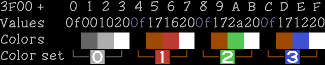
Consider the byte at $23F2:
 ,---- Top left
 3 1 - Top right
 2 2 - Bottom right
 `---- Bottom left
The byte has color set 2 at bottom right, 2 at bottom left, 1 at top right, and 3 at top left. Thus its attribute is calculated as follows:
value = (bottomright << 6) | (bottomleft << 4) | (topright << 2) | (topleft << 0)
      = (2           << 6) | (2          << 4) | (1        << 2) | (3       << 0)
      = $80                | $20               | $04             | $03
      = $A7
To find the address of an attribute byte corresponding to a nametable address, see: PPU scrolling: Tile and attribute fetching
Glitches
There are some well-known glitches when rendering attributes in NES and Famicom games.
While the attribute table specifies one of four three-color palettes for each 16x16 pixel region, the left-side clipping window in PPUMASK ($2001) is only 8 pixels wide.
This is the reason why games that use either horizontal or vertical mirroring modes for arbitrary-direction scrolling often have color artifacts on one side of the screen (on the right side in Super Mario Bros. 3; on the trailing side of the scroll in Kirby's Adventure; and at the top and bottom in Super C).
The game Alfred Chicken hides glitches on the left and right sides by using both left clipping and hiding the right side of the screen under solid-colored sprites. To mask the entire 240-scanline height, this approach would occupy 15 entries of 64 in the sprite table in 8x16 sprite mode, or 30 entries in the 8x8 mode.
See also
Palettes
The NES has a limited selection of color outputs. A 6-bit value in the palette memory area corresponds to one of 64 outputs. The emphasis bits of the PPUMASK register ($2001) provide an additional color modifier.
For more information on how the colors are generated on an NTSC NES, see: NTSC video
Memory Map
The palette for the background runs from VRAM $3F00 to $3F0F; the palette for the sprites runs from $3F10 to $3F1F. Each color takes up one byte.
| Address | Purpose |
|---|---|
| $3F00 | Universal background color |
| $3F01-$3F03 | Background palette 0 |
| $3F05-$3F07 | Background palette 1 |
| $3F09-$3F0B | Background palette 2 |
| $3F0D-$3F0F | Background palette 3 |
| $3F11-$3F13 | Sprite palette 0 |
| $3F15-$3F17 | Sprite palette 1 |
| $3F19-$3F1B | Sprite palette 2 |
| $3F1D-$3F1F | Sprite palette 3 |
Each palette has three colors. Each 16x16 pixel area of the background can use the backdrop color and the three colors from one of the four background palettes. The choice of palette for each 16x16 pixel area is controlled by bits in the attribute table at the end of each nametable. Each sprite can use the three colors from one of the sprite palettes. The choice of palette is in attribute 2 of each sprite (see PPU OAM).
Addresses $3F04/$3F08/$3F0C can contain unique data, though these values are not used by the PPU when normally rendering (since the pattern values that would otherwise select those cells select the backdrop color instead). They can still be shown using the background palette hack, explained below.
Addresses $3F10/$3F14/$3F18/$3F1C are mirrors of $3F00/$3F04/$3F08/$3F0C. Note that this goes for writing as well as reading. A symptom of not having implemented this correctly in an emulator is the sky being black in Super Mario Bros., which writes the backdrop color through $3F10.
Thus, indices into the palette are formed as follows:
43210
|||||
|||++- Pixel value from tile data
|++--- Palette number from attribute table or OAM
+----- Background/Sprite select
As in some second-generation game consoles, values in the NES palette are based on hue and brightness:
76543210
||||||||
||||++++- Hue (phase, determines NTSC/PAL chroma)
||++----- Value (voltage, determines NTSC/PAL luma)
++------- Unimplemented, reads back as 0
Hue $0 is light gray, $1-$C are blue to red to green to cyan, $D is dark gray, and $E-$F are mirrors of $1D (black). The canonical code for "black" is $0F or $1D. $0D should not be used; it results in a "blacker than black" signal that may cause problems for some TVs. It works this way because of the way colors are represented in an NTSC or PAL signal, with the phase of a color subcarrier controlling the hue. For details, see NTSC video, or for a list see Color $0D games.
The 2C03 RGB PPU used in the PlayChoice-10 and Famicom Titler renders hue $D as black, not dark gray. The 2C04 PPUs used in many Vs. System arcade games have completely different palettes as a copy protection measure.
Palettes
2C02

The RF Famicom, AV Famicom, NES (both front- and top-loading), and the North American version of the Sharp Nintendo TV use the 2C02 PPU. Unlike some other consoles' video circuits, the 2C02 does not generate RGB video and then encode that to composite. Instead it generates NTSC video directly in the composite domain, decoded by the television receiver into RGB to drive its picture tube.
Most emulators can use a predefined palette, such as one commonly stored in Classic VGA Palette format (.pal), in which each triplet represents the sRGB color that results from decoding a large flat area with a given palette value. The following table was generated using blargg's Full Palette demo on Nestopia:
 84  84  84    0  30 116    8  16 144   48   0 136   68   0 100   92   0  48   84   4   0   60  24   0   32  42   0    8  58   0    0  64   0    0  60   0    0  50  60    0   0   0
152 150 152    8  76 196   48  50 236   92  30 228  136  20 176  160  20 100  152  34  32  120  60   0   84  90   0   40 114   0    8 124   0    0 118  40    0 102 120    0   0   0
236 238 236   76 154 236  120 124 236  176  98 236  228  84 236  236  88 180  236 106 100  212 136  32  160 170   0  116 196   0   76 208  32   56 204 108   56 180 204   60  60  60
236 238 236  168 204 236  188 188 236  212 178 236  236 174 236  236 174 212  236 180 176  228 196 144  204 210 120  180 222 120  168 226 144  152 226 180  160 214 228  160 162 160
Other tools for generating a palette include one by Bisqwit and one by Drag. These simulate generating a large area of one flat color and then decoding that with the adjustment knobs set to various settings.
The 2C03, 2C04, and 2C05, on the other hand, all output analog red, green, blue, and sync (RGBS) signals. The sync signal contains horizontal and vertical sync pulses in the same format as an all-black composite signal. Each of the three video channels uses a 3-bit DAC driven by a look-up table in a 64x9-bit ROM inside the PPU. The look-up tables (one digit for each of red, green, and blue, in order) are given below:
2C03 and 2C05
This palette is intentionally similar to the NES's standard palette, but notably is missing the greys in entries $2D and $3D.
The 2C03 is used in Vs. Duck Hunt, Vs. Tennis, all PlayChoice games, the Famicom Titler, and the Famicom TV.
The 2C05 is used in some later Vs. games as a copy protection measure.
Both have been used in RGB mods for the NES, as a circuit implementing A0' = A0 xor (A1 nor A2) can swap PPUCTRL and PPUMASK to make a 2C05 behave as a 2C03.
333,014,006,326,403,503,510,420,320,120,031,040,022,000,000,000
555,036,027,407,507,704,700,630,430,140,040,053,044,000,000,000
777,357,447,637,707,737,740,750,660,360,070,276,077,000,000,000
777,567,657,757,747,755,764,772,773,572,473,276,467,000,000,000
| 0x00 | 0x01 | 0x02 | 0x03 | 0x04 | 0x05 | 0x06 | 0x07 | 0x08 | 0x09 | 0x0A | 0x0B | 0x0C | 0x0D | 0x0E | 0x0F |
| 0x10 | 0x11 | 0x12 | 0x13 | 0x14 | 0x15 | 0x16 | 0x17 | 0x18 | 0x19 | 0x1A | 0x1B | 0x1C | 0x1D | 0x1E | 0x1F |
| 0x20 | 0x21 | 0x22 | 0x23 | 0x24 | 0x25 | 0x26 | 0x27 | 0x28 | 0x29 | 0x2A | 0x2B | 0x2C | 0x2D | 0x2E | 0x2F |
| 0x30 | 0x31 | 0x32 | 0x33 | 0x34 | 0x35 | 0x36 | 0x37 | 0x38 | 0x39 | 0x3A | 0x3B | 0x3C | 0x3D | 0x3E | 0x3F |
Kevtris's dumped palettes imply that the monochrome bit has unique function on the 2C03 and 2C05: instead of just using the leftmost column of the palette (and forcing the lower four bits to zero), instead the top two bits index into a palette with colors: 000, 333, 777, 777. Given that the 2C04 does not do this, this exception feels weird, and corroboration would be appreciated.
RC2C03B
For no particularly discernible reason, the palette for this specific PPU varies in six colors:
333,014,006,326,403,503,510,420,320,100,031,040,022,000,000,000
555,016,027,407,507,704,700,630,430,140,040,053,044,000,000,000
777,357,447,637,707,717,740,750,660,340,070,276,077,000,000,000
777,547,657,757,747,755,764,772,773,552,473,276,467,000,000,000
| 0x00 | 0x01 | 0x02 | 0x03 | 0x04 | 0x05 | 0x06 | 0x07 | 0x08 | 0x09 | 0x0a | 0x0b | 0x0c | 0x0d | 0x0e | 0x0f |
| 0x10 | 0x11 | 0x12 | 0x13 | 0x14 | 0x15 | 0x16 | 0x17 | 0x18 | 0x19 | 0x1a | 0x1b | 0x1c | 0x1d | 0x1e | 0x1f |
| 0x20 | 0x21 | 0x22 | 0x23 | 0x24 | 0x25 | 0x26 | 0x27 | 0x28 | 0x29 | 0x2a | 0x2b | 0x2c | 0x2d | 0x2e | 0x2f |
| 0x30 | 0x31 | 0x32 | 0x33 | 0x34 | 0x35 | 0x36 | 0x37 | 0x38 | 0x39 | 0x3a | 0x3b | 0x3c | 0x3d | 0x3e | 0x3f |
The pattern compared to the normal 2C03 is that where color bits 0-1 are 01 (i.e. palette entries 0x01/0x11/0x21/0x31, 0x05/0x15/0x25/0x35, and 0x09/0x19/0x29/0x39), green is ANDed with 5 (bit 1 is 0). No games are known to be designed for this palette. Given the pattern, it was probably a mistake in the mask.
2C04
All four 2C04 PPUs contain the same master palette, but in different permutations. It's almost a superset of the 2C03/5 palette, adding four greys, six other colors, and making the bright yellow more pure.
No version of the 2C04 was ever made with the below ordering, but it shows the similarity to the 2C03:
| 333 | 014 | 006 | 326 | 403 | 503 | 510 | 420 | 320 | 120 | 031 | dup of ↙ | 022 | 111 | 003 | 020 |
| 555 | 036 | 027 | 407 | 507 | 704 | 700 | 630 | 430 | 140 | 040 | 053 | 044 | 222 | 200 | 310 |
| 777 | 357 | 447 | 637 | 707 | 737 | 740 | 750 | 660 | 360 | 070 | dup of ↓ | 077 | 444 | 000 | 000 |
| 777 | 567 | 657 | 757 | 747 | 755 | 764 | 770 | 773 | 572 | 473 | 276 | 467 | 666 | 653 | 760 |
The PPUMASK monochrome bit has the same implementation as on the 2C02, and so it has an unintuitive effect on the 2C04 PPUs; rather than forcing colors to grayscale, it instead forces them to the first column.
RP2C04-0001
MAME's source claims that Baseball, Freedom Force, Gradius, Hogan's Alley, Mach Rider, Pinball, and Platoon require this palette.
755,637,700,447,044,120,222,704,777,333,750,503,403,660,320,777
357,653,310,360,467,657,764,027,760,276,000,200,666,444,707,014
003,567,757,070,077,022,053,507,000,420,747,510,407,006,740,000
000,140,555,031,572,326,770,630,020,036,040,111,773,737,430,473
RP2C04-0002
MAME's source claims that Castlevania, Mach Rider (Endurance Course), Raid on Bungeling Bay, Slalom, Soccer, Stroke & Match Golf (both versions), and Wrecking Crew require this palette.
000,750,430,572,473,737,044,567,700,407,773,747,777,637,467,040
020,357,510,666,053,360,200,447,222,707,003,276,657,320,000,326
403,764,740,757,036,310,555,006,507,760,333,120,027,000,660,777
653,111,070,630,022,014,704,140,000,077,420,770,755,503,031,444
RP2C04-0003
MAME's source claims that Balloon Fight, Dr. Mario, Excitebike (US), Goonies, and Soccer require this palette.
507,737,473,555,040,777,567,120,014,000,764,320,704,666,653,467
447,044,503,027,140,430,630,053,333,326,000,006,700,510,747,755
637,020,003,770,111,750,740,777,360,403,357,707,036,444,000,310
077,200,572,757,420,070,660,222,031,000,657,773,407,276,760,022
RP2C04-0004
MAME's source claims that Clu Clu Land, Excitebike (Japan), Ice Climber (both versions), and Super Mario Bros. require this palette.
430,326,044,660,000,755,014,630,555,310,070,003,764,770,040,572
737,200,027,747,000,222,510,740,653,053,447,140,403,000,473,357
503,031,420,006,407,507,333,704,022,666,036,020,111,773,444,707
757,777,320,700,760,276,777,467,000,750,637,567,360,657,077,120
Backdrop color (palette index 0) uses
During forced blanking, when neither background nor sprites are enabled in PPUMASK ($2001), the picture will show the backdrop color. If only the background or sprites are disabled, or if the left 8 pixels are clipped off, the PPU continues its normal video memory access pattern but uses the backdrop color for anything disabled.
The background palette hack
If the current VRAM address points in the range $3F00-$3FFF during forced blanking, the color indicated by this palette location will be shown on screen instead of the backdrop color. (Looking at the relevant circuitry in Visual 2C02, this is an intentional feature of the PPU and not merely a side effect of how rendering works.) This can be used to display colors from the normally unused $3F04/$3F08/$3F0C palette locations. A loop that fills the palette will cause each color in turn to be shown on the screen, so to avoid horizontal rainbow bar glitches while loading the palette, wait for a real vertical blank first using an NMI technique.
Color names
When programmers and artists are communicating, it's often useful to have human-readable names for colors. Many graphic designers who have done web or game work will be familiar with HTML color names.
Luma
- $0F: Black
- $00: Dark gray
- $10: Light gray or silver
- $20: White
- $01-$0C: Dark colors, medium mixed with black
- $11-$1C: Medium colors, similar brightness to dark gray
- $21-$2C: Light colors, similar brightness to light gray
- $31-$3C: Pale colors, light mixed with white
Chroma
Names for hues:
- $x0: Gray
- $x2: Blue
- $x4: Magenta
- $x6: Red
- $x7: Orange
- $x8: Yellow or olive
- $xA: Green
- $xC: Cyan
RGBI
These NES colors approximate colors in 16-color RGBI palettes, such as the CGA, EGA, or classic Windows palette, though the NES doesn't really have a good yellow:
- $02: Navy
- $06: Maroon
- $12: Blue
- $14: Purple
- $16: Red
- $17: Brown
- $18: Olive
- $1A: Green
- $1C: Aqua
- $24: Fuchsia/Magenta
- $2A: Lime
- $2C: Teal
See also
- NTSC video - details of the NTSC signal generation and how it produces the palette
- PAL video
- PPU_palettes/zh - this page in Chinese
Memory map
PPU memory map
The PPU addresses a 16kB space, $0000-3FFF, completely separate from the CPU's address bus. It is either directly accessed by the PPU itself, or via the CPU with memory mapped registers at $2006 and $2007.
The NES has 2kB of RAM dedicated to the PPU, normally mapped to the nametable address space from $2000-2FFF, but this can be rerouted through custom cartridge wiring.
| Address range | Size | Description |
|---|---|---|
| $0000-$0FFF | $1000 | Pattern table 0 |
| $1000-$1FFF | $1000 | Pattern table 1 |
| $2000-$23FF | $0400 | Nametable 0 |
| $2400-$27FF | $0400 | Nametable 1 |
| $2800-$2BFF | $0400 | Nametable 2 |
| $2C00-$2FFF | $0400 | Nametable 3 |
| $3000-$3EFF | $0F00 | Mirrors of $2000-$2EFF |
| $3F00-$3F1F | $0020 | Palette RAM indexes |
| $3F20-$3FFF | $00E0 | Mirrors of $3F00-$3F1F |
In addition, the PPU internally contains 256 bytes of memory known as Object Attribute Memory which determines how sprites are rendered. The CPU can manipulate this memory through memory mapped registers at OAMADDR ($2003), OAMDATA ($2004), and OAMDMA ($4014). OAM can be viewed as an array with 64 entries. Each entry has 4 bytes: the sprite Y coordinate, the sprite tile number, the sprite attribute, and the sprite X coordinate.
| Address Low Nibble | Description |
|---|---|
| $00, $04, $08, $0C | Sprite Y coordinate |
| $01, $05, $09, $0D | Sprite tile # |
| $02, $06, $0A, $0E | Sprite attribute |
| $03, $07, $0B, $0F | Sprite X coordinate |
Hardware mapping
The mappings above are the fixed addresses from which the PPU uses to fetch data during rendering. The actual device that the PPU fetches data from, however, may be configured by the cartridge.
- $0000-1FFF is normally mapped by the cartridge to a CHR-ROM or CHR-RAM, often with a bank switching mechanism.
- $2000-2FFF is normally mapped to the 2kB NES internal VRAM, providing 2 nametables with a mirroring configuration controlled by the cartridge, but it can be partly or fully remapped to RAM on the cartridge, allowing up to 4 simultaneous nametables.
- $3000-3EFF is usually a mirror of the 2kB region from $2000-2EFF. The PPU does not render from this address range, so this space has negligible utility.
- $3F00-3FFF is not configurable, always mapped to the internal palette control.