Drawing overview
The PPU outputs a picture region of 256x240 pixels and a border region extending 16 pixels left, 11 pixels right, and 2 pixels down (283x242). The picture region is generated by doing memory fetches that fill shift registers, from which a pixel is selected. It is composed of a background region filling the entire screen and smaller sprites that may be placed nearly anywhere on it. In the border and any transparent pixel, the PPU displays the palette index selected by the PPU's EXT input, which is grounded to index 0 in stock consoles.
Picture region
                                         [BBBBBBBB] - Next tile's pattern data,
                                         [BBBBBBBB] - 2 bits per pixel
                                          ||||||||<----[Transfers every inc hori(v)]
                                          vvvvvvvv
      Serial-to-parallel - [AAAAAAAA] <- [BBBBBBBB] <- [1...] - Parallel-to-serial
         shift registers - [AAAAAAAA] <- [BBBBBBBB] <- [1...] - shift registers
                            vvvvvvvv
                            ||||||||   [Sprites 0..7]----+  [EXT in]----+
                            ||||||||                     |              |
[fine_x selects a bit]---->[  Mux   ]------------>[Priority mux]----->[Mux]---->[Pixel]
                            ||||||||                              |
                            ^^^^^^^^                              +------------>[EXT out]
      Serial-to-parallel - [PPPPPPPP] <- [P] - 1-bit latch
         shift registers - [PPPPPPPP] <- [P] - 1-bit latch
                                          ^
                                          |<--------[Transfers every inc hori(v)]
                                     [  Mux   ]<----[coarse_x bit 1 and coarse_y bit 1 select 2 bits]
                                      ||||||||
                                      ^^^^^^^^
                                     [PPPPPPPP] - Next tile's attributes data
To generate the background in the picture region, the PPU performs memory fetches on dots 321-336 and 1-256 of scanlines 0-239 and 261. Each memory fetch takes 2 dots: on the 1st, the full address is placed onto the PPU's address bus and the low 8 bits are stored into an external address latch, and on the 2nd, the read is performed. Fetches require 2 dots because the same physical pins are used for the data bus and low 8 bits of address, so the address must be latched externally before a read can be done.
In each 8-dot window, the PPU performs the 4 memory fetches required to produce 8 pixels, fully occupying the PPU bus. Using the current scroll register, v, to produce the target addresses, the PPU fetches a tile ID from the nametable, attributes data from the attributes table, and the low and then high bitplane of the pattern data for that tile ID. The fetched bytes are stored in internal registers.
On every 8th dot in these background fetch regions (the same dot on which the coarse x component of v is incremented), the pattern and attributes data are transferred into registers used for producing pixel data. For the pattern data, these transfers are into the high 8 bits of two 16-bit shift registers. For the attributes data, only 2 bits are transferred and into two 1-bit latches that feed 8-bit shift registers. The concept for both is the same, differing merely because the attributes data is the same for all 8 pixels, negating the need to store 8 copies of it.
On every dot in these background fetch regions, a 4-bit pixel is selected by the fine x register from the low 8 bits of the pattern and attributes shift registers, which are then shifted.
The PPU then selects between this background pixel and the 4-bit sprite pixel produced by the OAM process. This selection depends on whether each pixel is transparent (low 2 bits are both 0) and the sprite's priority (whether it appears in front of (0) or behind (1) the background). If both are transparent, the background pixel is selected. After the selection, the pixel is now 5-bit, with the new top bit determined by whether background (0) or sprites (1) was selected. If the PPU is configured to output on its EXT pins, it outputs the low 4 bits of the selected pixel.
If the selected pixel is transparent, it is replaced with the EXT input: bit 4 is always 0, and bits 3-0 take the values of EXT3-0. The PPU's 4 EXT pins are grounded in all known console variations, so this input is normally 0. If the PPU is configured for EXT output, then the input value is always 0. (However, because these pins are grounded, EXT should never be in output mode because it could cause physical damage.)
The result of all of this is a 5-bit index used to look up a value from palette RAM. This value is a color, which can be modified by the emphasis and greyscale features of the PPUMASK register and is then drawn as a pixel.
As-used, EXT input always produces an all-0 value, so transparent pixels always display the color at $3F00 in palette RAM, referred to as the 'backdrop' color.
| BG pixel | Sprite pixel | Priority | Output |
|---|---|---|---|
| 0 | 0 | X | EXT in ($3F00) |
| 0 | 1-3 | X | Sprite |
| 1-3 | 0 | X | BG |
| 1-3 | 1-3 | 0 | Sprite |
| 1-3 | 1-3 | 1 | BG |
Notes:
- Sprite have a 1-bit priority relative to backgrounds, but they also have a priority relative to each other depending on their order in OAM. Lower sprite indices are higher priority than higher indices, and the highest priority sprite pixel is selected before background priority is handled. Because of this, a high priority sprite in the background takes precedence over a lower priority sprite even in the foreground, which can cause the background to appear in front of that foreground sprite, referred to as the sprite priority quirk.
- Reads come from an address composed of the latched low 8 bits and the current high 6 bits. If rendering is toggled, these can become desynced, producing a hybrid address sourced from two different addresses and reading from an address the PPU itself never actually outputted.
- The 16-bit pattern shift registers shift in 1's. Normally, these are clobbered by the next pattern data load, but toggling rendering mid-frame may allow more than 8 shifts between loads, allowing these 1's to be rendered.
- The storage registers, shift registers, and 1-bit latches described here decay to 0 on a time scale of probably around 2 frames. The results of this decay may be visible when turning rendering on mid-frame.
- Bits leaving the attributes and low pattern data registers are inverted, and then inverted back before the background/sprite priority mux. Because of this, if they decay to 0, they actually end up as 1's in the output, and any 1's resulting from extra shifts in the low pattern shift register end up as 0's.
Border region
The border region displays the palette RAM entry selected by EXT input, either the data on the EXT pins if in input mode or 0 if in output mode. The first pixel on the left border is displayed with greyscale mode enabled. The border is affected by PPUMASK emphasis and greyscale effects.
Rendering disabled
With rendering disabled, both the picture and border regions display only EXT input. On PPUs that support CPU reads from palette RAM (RP2C02G, RP2C02H), the automatic greyscale effect on the first border pixel is disabled if a CPU palette read occurs at the exact same time.[1]
When the PPU isn't rendering, its v register specifies the current VRAM address (and is output on the PPU's address pins). Whenever the low 14 bits of v point into palette RAM ($3F00-$3FFF), the PPU will continuously draw the color at that address instead of the EXT input, overriding the backdrop color. This is because the only way to access palette RAM is with this drawing mechanism, and is akin to color RAM dots on consoles such as the Master System and Mega Drive / Genesis. Backdrop override is used intentionally by some software.
PPUMASK emphasis and greyscale effects apply even with rendering disabled.
PAL
PAL PPUs have the same rendering behavior as NTSC PPUs except for the border. The border is always black and extends 1 pixel into the top and 2 pixels into each of the left and right edges of the picture region, whether rendering is enabled or not. Emphasis and greyscale effects do not apply to this border. Note that this border does not change the behavior of sprite 0 hit compared to NTSC.
Line-by-line timing
The PPU renders 262 scanlines per frame. Each scanline lasts for 341 PPU clock cycles (113.667 CPU clock cycles; 1 CPU cycle = 3 PPU cycles), with each clock cycle producing one pixel. The line numbers given here correspond to how the internal PPU frame counters count lines.
The information in this section is summarized in the diagram in the next section.
The timing below is for NTSC PPUs. PPUs for 50 Hz TV systems differ:
- Dendy PPUs render 51 post-render scanlines instead of 1
- PAL NES PPUs render 70 vblank scanlines instead of 20, and they additionally run 3.2 PPU cycles per CPU cycle, or 106.5625 CPU clock cycles per scanline.
Pre-render scanline (-1 or 261)
This is a dummy scanline, whose sole purpose is to fill the shift registers with the data for the first two tiles of the next scanline. Although no pixels are rendered for this scanline, the PPU still makes the same memory accesses it would for a regular scanline, using whatever the current value of the PPU's V register is, and for the sprite fetches, whatever data is currently in secondary OAM (e.g., the results from scanline 239's sprite evaluation from the previous frame).
This scanline varies in length, depending on whether an even or an odd frame is being rendered. For odd frames, the cycle at the end of the scanline is skipped (this is done internally by jumping directly from (339,261) to (0,0), replacing the idle tick at the beginning of the first visible scanline with the last tick of the last dummy nametable fetch). For even frames, the last cycle occurs normally. This is done to compensate for some shortcomings with the way the PPU physically outputs its video signal, the end result being a crisper image when the screen isn't scrolling. However, this behavior can be bypassed by keeping rendering disabled until after this scanline has passed, which results in an image with a "dot crawl" effect similar to, but not exactly like, what's seen in interlaced video.
During pixels 280 through 304 of this scanline, the vertical scroll bits are reloaded if rendering is enabled.
Visible scanlines (0-239)
These are the visible scanlines, which contain the graphics to be displayed on the screen. This includes the rendering of both the background and the sprites. During these scanlines, the PPU is busy fetching data, so the program should not access PPU memory during this time, unless rendering is turned off.
Cycle 0
This is an idle cycle. The value on the PPU address bus during this cycle appears to be the same CHR address that is later used to fetch the low background tile byte starting at dot 5 (possibly calculated during the two unused NT fetches at the end of the previous scanline).
Cycles 1-256
The data for each tile is fetched during this phase. Each memory access takes 2 PPU cycles to complete, and 4 must be performed per tile:
- Nametable byte
- Attribute table byte
- Pattern table tile low
- Pattern table tile high (+8 bytes from pattern table tile low)
The data fetched from these accesses is placed into internal latches, and then fed to the appropriate shift registers when it's time to do so (every 8 cycles). Because the PPU can only fetch an attribute byte every 8 cycles, each sequential string of 8 pixels is forced to have the same palette attribute.
Sprite 0 hit acts as if the image starts at cycle 2 (which is the same cycle that the shifters shift for the first time), so the sprite 0 flag will be raised at this point at the earliest. Actual pixel output is delayed further due to internal render pipelining, and the first pixel is output during cycle 4.
The shifters are reloaded during ticks 9, 17, 25, ..., 257.
Note: At the beginning of each scanline, the data for the first two tiles is already loaded into the shift registers (and ready to be rendered), so the first tile that gets fetched is Tile 3.
While all of this is going on, sprite evaluation for the next scanline is taking place as a seperate process, independent to what's happening here.
Cycles 257-320
The tile data for the sprites on the next scanline are fetched here. Again, each memory access takes 2 PPU cycles to complete, and 4 are performed for each of the 8 sprites:
- Garbage nametable byte
- Garbage nametable byte
- Pattern table tile low
- Pattern table tile high (+8 bytes from pattern table tile low)
The garbage fetches occur so that the same circuitry that performs the BG tile fetches could be reused for the sprite tile fetches.
If there are less than 8 sprites on the next scanline, then dummy fetches to tile $FF occur for the left-over sprites, because of the dummy sprite data in the secondary OAM (see sprite evaluation). This data is then discarded, and the sprites are loaded with a transparent set of values instead.
In addition to this, the X positions and attributes for each sprite are loaded from the secondary OAM into their respective counters/latches. This happens during the second garbage nametable fetch, with the attribute byte loaded during the first tick and the X coordinate during the second.
Cycles 321-336
This is where the first two tiles for the next scanline are fetched, and loaded into the shift registers. Again, each memory access takes 2 PPU cycles to complete, and 4 are performed for the two tiles:
- Nametable byte
- Attribute table byte
- Pattern table tile low
- Pattern table tile high (+8 bytes from pattern table tile low)
Cycles 337-340
Two bytes are fetched, but the purpose for this is unknown. These fetches are 2 PPU cycles each.
- Nametable byte
- Nametable byte
Both of the bytes fetched here are the same nametable byte that will be fetched at the beginning of the next scanline (tile 3, in other words). At least one mapper -- MMC5 -- is known to use this string of three consecutive nametable fetches to clock a scanline counter.
Post-render scanline (240)
The PPU just idles during this scanline. Even though accessing PPU memory from the program would be safe here, the VBlank flag isn't set until after this scanline.
Vertical blanking lines (241-260)
The VBlank flag of the PPU is set at tick 1 (the second tick) of scanline 241, where the VBlank NMI also occurs. The PPU makes no memory accesses during these scanlines, so PPU memory can be freely accessed by the program.
PPU address bus contents
During frame rendering, provided rendering is enabled (i.e., when either background or sprite rendering is enabled in $2001:3-4), the value on the PPU address bus is as indicated in the descriptions above and in the frame timing diagram below. During VBlank and when rendering is disabled, the value on the PPU address bus is the current value of the v register.
To save pins, the PPU multiplexes the lower eight VRAM address pins, also using them as the VRAM data pins. This leads to each VRAM access taking two PPU cycles:
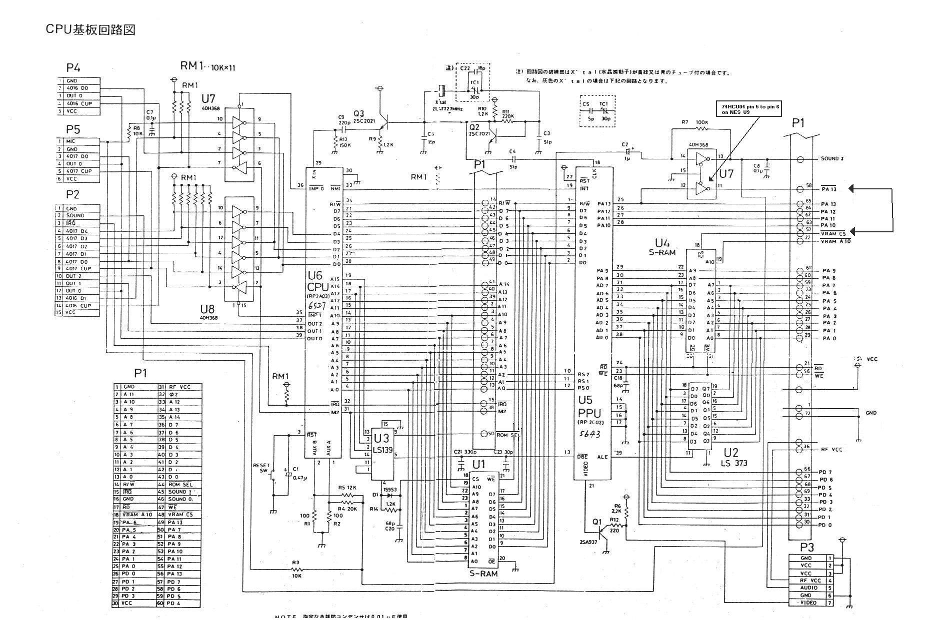
- During the first cycle, the entire VRAM address is output on the PPU address pins and the lower eight bits stored in an external octal latch by asserting the ALE (Address Latch Enable) line. (The octal latch is the lower chip to the right of the PPU in this wiring diagram.)
- During the second cycle, the PPU only outputs the upper six bits of the address, with the octal latch providing the lower eight bits (VRAM addresses are 14 bits long). During this cycle, the value is read from or written to the lower eight address pins.
As an example, the PPU VRAM address pins will have the value $2001 followed by the value $20AB for a read from VRAM address $2001 that returns the value $AB.
Frame timing diagram

See also
References
- ↑ Forum post: Fiskbit's greyscale_column_sparkle_test